Research Article, J Nucl Ene Sci Power Generat Technol Vol: 11 Issue: 4
Vienna Rectifier Control Using SPWM and SVPWM for EV Charging Station
Sweety Jose P1* and Muthulakshmi M2
1Department of Physics, SGT University, Gurugram, Haryana,India
2Department of Electrical and Electronic Engineering, Teerthanker Mahaveer University, Uttar Pradesh, India
*Corresponding Author :Sweety Jose P, Department of Physics, SGT University, Gurugram, Haryana, India; E-mail: josesweety_agriculture@sgtuniversity.org
Received date: 03 November, 2021, Manuscript No. JNPGT-21-46544;
Editor assigned date: 05 November, 2021, PreQC No. JNPGT-21-46544 (PQ);
Reviewed date: 19 November, 2021, QC No. JNPGT-21-46544;
Revised date: 03 January 2022, Manuscript No. JNPGT-21-46544 (R);
Published date: 23 March 2022, DOI: 10.4172/2325-9809.1000259
Citation: Sweety Jose P, Muthulakshmi M (2022) Vienna Rectifier Control Using SPWM and SVPWM for EV Charging Station. J Nucl Ene Sci Power Generat Technol 11:4.
Abstract
Electric vehicles are an evolving technology in today's world that will eventually replace internal combustion engine-powered automobiles in order to mitigate global warming. For Electric Vehicle (EV) charging stations that are connected to the grid, power quality is critical in order to meet IEEE-519 requirements. As a result, for the Fast DC charging application, the Vienna Rectifier is used as a frond end converter. The Vienna rectifier is the best choice for high-power applications because it helps to increase output voltage while reducing ripple and improving current efficiency. In this paper, the control techniques of Sinusoidal Pulse Width Modulation (SPWM) and Space Vector Pulse Width Modulation (SVPWM) are compared and the results are obtained. The Vienna rectifier is used to minimize switching loss and achieve low THD while maintaining unity power factor. The grid side of this rectifier achieves sinusoidal current. It also has fewer switches and is simpler since it uses a unidirectional power flow to pass power from the grid to the EV's battery. MATLAB/SIMULINK is used to analyse and verify both control techniques with the designed Vienna rectifier topology, and the results are compared. The designed rectifier is used in this application for a Level 3 EV charging station with a 30 kW battery load.
Keywords: Space vector control, Vienna rectifier, Harmonic, Power factor, Fast charging
Introduction
The AC-DC, DC-DC, and DC-AC types of power electronic converters play a critical role in EV charging stations. To provide enough energy for the vehicle during travel, EV batteries should be charged to a certain amount. Various EV battery chargers aim for quick or slow charging depending on the power rating and charging location. The topology of the Vienna rectifier used here is a three-phase, three-level, and three-switch (controllable) rectifier. Because of its high performance, high power density, and low THD, it has been widely used in a variety of high-power applications. It is possible to obtain a sinusoidal current waveform with low THD, high reliability, and high-power density [1].
The LCL filter is designed and used in the input side of the rectifier to minimise the input current quality. In comparison to traditional rectifiers, the AC filters needed in this rectifier are relatively tiny [2]. In this topology, switching losses are reduced while the converter boost ratio is increased. It is important for suppressing higher order harmonics produced during the switching process [3].
A 30 kW three-phase/level Vienna rectifier with sinusoidal input current, less than 5% current harmonic distortions on the supply side, and unity power factor is designed and implemented. The Vienna rectifier topology is presented, which includes the design process, system selection, SPWM and SVPWM control technique, inductor selection and battery output.
Materials and Methods
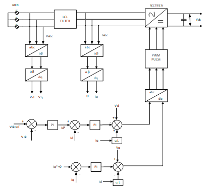
Vienna rectifierBlock diagram of DC charging: The simple Block diagram of DC charging with a Vienna rectifier is shown in Figure 1. Chargers are graded as Level 1, Level 2, or Level 3 chargers based on their power rating [4]. Level 1 and Level 2 chargers are equipped for home charging with a power consumption of 2 kW and a voltage of 120/230 V, respectively, and public charging stations with a power consumption of 20 kW, while Level 3 chargers are used for commercial charging stations that are directly connected to three-phase medium voltage systems.
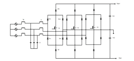
Topology of Vienna rectifierIn order to improve grid side current quality and minimise harmonics at input current, three phase power is used by equipment operating at high power applications. For DC loads, power factor correction is needed. Despite the fact that there are a variety of topologies for power factor correction, the Vienna rectifier is a popular choice due to its low harmonics, continuous conduction mode, and lower voltage stress on the devices [5]. The Vienna rectifier is operated using the Sinusoidal PWM and Space Vector PWM Control techniques are used and compared. Due to its low THD output, unity power factor, and high efficiency, the proposed converter consists of a three phase three switch Vienna rectifier, which is widely used for high power applications. Figure 2 shows the topology of Vienna Rectifier.
For proper system simulation detailed modelling Vienna rectifier with LCL filter [6] is needed. The SPWM and SVPWM technique is implemented for three switches.
Working of Vienna RectifierThe main aim of this topology is to increase the power factor, with a harmonic content of less than 5% on grid side current. It aids in improving the efficiency of the input current and designing a rectifier with less ripple for the EV battery. Vienna rectifier with output voltage regulation technique for boost derived three switch converters. The main benefit is that there are no harmonics at the input, and the process will continue even if the system is unbalanced. The inductor is charged when the switch is switched on, and it pushes the current through the bidirectional switch. The current bypasses the MOSFET switch and flows through the freewheeling diode when the switch is deactivated [7].
Control circuit for Vienna rectifierThe current control technique is used to control current on the d-axis and q-axis in the Vienna Rectifier. Clarke transformation and Park transformation convert three-phase voltage (Va, Vb, Vc) and three-phase current (Ia, Ib, Ic) into [8] d-q axis synchronous reference frame in current control.
The Figure 3 shows the control circuit for Vienna Rectifier. Id denotes the current on the d-axis compared to active power, while Iq denotes the current on the q-axis related to reactive power. As a result, Iq* is regulated as a zero value for the unity power factor, and Id* is provided from the outer loop dc bus voltage control by a Proportional-Integral [9] (PI) controller. It displays the dc-bus voltage balance and current control systems to produce the d-axis current reference, Id*, the PI controller controls the dc-link voltage, Vdc, in accordance with the dc-link voltage reference, Vdref. In a three-phase reference frame, the voltages on the d-q axes, Vd, Vq, are converted into Va, Vb, and Vc [10].
Sinusoidal pwm controlSinusoidal PWM is a typical PWM technique in which the sinusoidal AC voltage reference is compared with the high-frequency triangular carrier wave in real time to determine switching states for rectifier. In this technique, the switches can be turned ON and OFF based on cycle which results in a square waveform. However, if the switch is turned on for a number of times, a harmonic profile that is improved waveform is obtained. The sinusoidal PWM waveform is obtained by comparing the desired modulated waveform with a triangular waveform of high frequency. The resulting output voltage of the DC bus is either negative or positive.
Space vector PWM controlThe proposed Vienna Rectifier topology uses a diode and switches to switch between three states. Si Values of 0, +1, and -1 are used to represent the switching function. The voltage values vary between 0 Vdc/2 and -Vdc/2 depending on the Si value. The three-level SVPWM technique will improve the grid side input current quality and voltage [11].
Result and Discussion
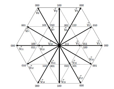
The Figure 4 illustrates the space vectors for Vienna Rectifier. Eight possible combinations can be achieved on and off patterns. The key benefit of using SVPWM control is that it reduces THD at grid side current and allows each sector to control its own PWM pulses. According to the hexagon, one three-level voltage space vector was taken from the hexagon of two-level voltage space vector, resulting in six two-level space vectors to locate the base vector and its switching period. Three level space vectors reference voltage values are converted into two level space vectors. The pulses are produced based on the vector configuration [12]. This transformation results in six vectors of non-zero voltage, and two vectors of zero. The non-zero vectors form the hexagon axes that comprise six sectors (V1-V6). The hexagon envelope generated by non-zero vectors is the locus of the maximum voltage output. SVPWM consists of regulating a vector's stator currents. This regulation is based on analysis which converts a time-and frequency-dependent three-phase system it into two-coordinate time invariant model (coordinates d and q).
Design specificationThe specifications for the design of 3-phase, 3-level rectifier has been shown in Table 1. Assumptions made are the input current to be a pure sinusoid and the rectifier to be operating at UPF with Efficiency of 98.5%. The Vienna rectifier and LCL filter designed (Table 2).
| S. no. | Parameter | Value |
|---|---|---|
| 1 | RMS voltage, Vrms | 400 V |
| 2 | Input voltage, Vin | 326 V |
| 3 | Ripple voltage, △Vc | 0.2 |
| 4 | Output voltage, Vo | 700 V |
| 5 | Output power, Po | 30 kW |
| 6 | Efficiency,η | 0.985 |
| 7 | Switching frequency, Fsw | 20 kHz |
| 8 | Battery voltage | 700 V |
| 9 | Battery capacity | 50 Ah |
| 10 | Battery type | Lithium ion |
Table 1: Design specification for Vienna rectifier.
| Formulas | Calculated Values |
|---|---|
| δ=(Vo-Vin)/Vo | 0.534 |
| M=Vo/(sqrt (3) *Vin) | 1.23 |
| Pin=Pout/η | 30.45 kW |
| IN=Pin/(3*Vrms) | 25.3 A |
| ID,avg=IN/(2*sqrt (3) *M) | 5.95 A |
| ID,rms=IN/(sqrt(4/3*sqrt(3)*π*M) | 11 A |
| Icout=IN*sqrt((5/(2*π*M) – (3/(4*M2))) | 10 A |
| IPK=(sqrt (2) *Pin)/(sqrt (3) *PF*Vin) | 62 A |
| L=(Vin* δ)/(Fsw* IPK) | 200 μH |
| C=(Icout* δ)/(Fsw* △Vc) | 2800 μF |
Table 2: Design calculations for Vienna rectifier.
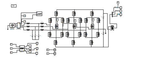
Math lab modellingSimulink model of the three phase Vienna rectifier is shown in Figure 5. The bidirectional diodes are used to simulate the three-phase Vienna rectifier, which consists of six diodes with a single MOSFET switch. The output of the diode is then fed to a DC connection capacitor, which is connected to a 30 kW battery load. The reference voltage is fed to the SPWM and SVPWM with the closed loop circuitperformed with a PI controller with Clarke and Park transform. The load attached is a lithium ion battery.
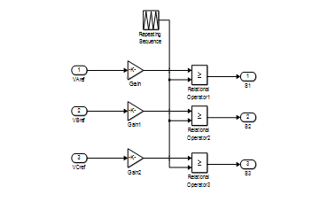
The Figure 6 shows the pulse produced by comparing the input voltage’s reference value to the carrier signal which fed to the MOSFET Switches.
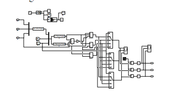
The Figure 7 displays the switching pattern for sector controls 0° through 360°.
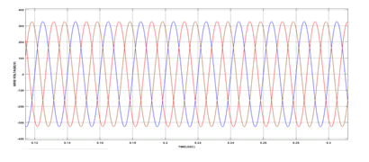
The Figure 8 shows the input voltage waveform of a Vienna rectifier with 400 Vrms.
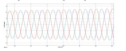
The Figure 9 shows the input current of 12 A for SPWM Control.
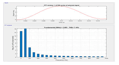
The THD at the grid side current in SPWM control is 7%, as seen in Figure 10 above.
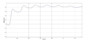
The Power factor of 0.71 in SPWM control is shown in Figure 11 above, and it can be improved by achieving better current efficiency.
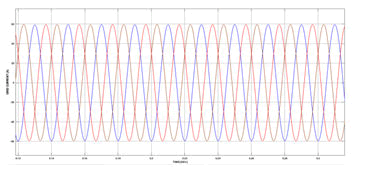
The Figure 12 shows the input current of 60 A, this waveform displays the input current of a Vienna rectifier with good input current accuracy.
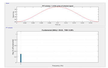
The THD at the grid side current in SVPWM control is 0.28%, as shown in Figure 13.
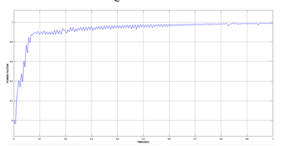
The Power factor of 0.99 in SVPWM control is shown Figure 14, and it can be improved by achieving better current efficiency [13].
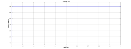
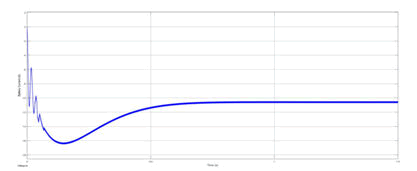
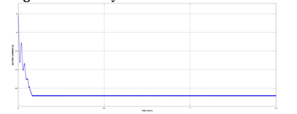
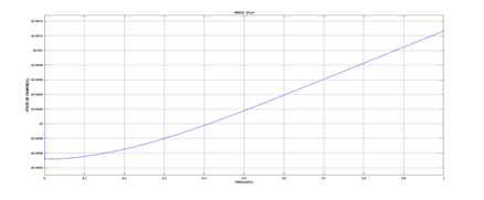
Battery voltage, battery current and battery SOC are shown in Figure 15, Figure 16, Figure 17 and Figure 18 respectively. This Waveform shows the state of charge reaches 30% when the rated capacity is reached that when it attains the rated voltage of 700 V [14].
Conclusion
In this paper, MATLAB/Simulink software is used to model and evaluate the Vienna Rectifier's output in terms of power factor and THD. The proposed converter has a higher power factor in the ac mains and lower input current THD. In terms of efficiency, THD, and power factor, the Vienna Rectifier is a better power converter for electric vehicle charging stations. Here, the THD and Power factor of the SPWM and SVPWM are analysed and compared. The THD in SPWM control is around 7% with a power factor of 0.71, while the THD in SVPWM control is around 0.28% with a power factor of 0.99. As a result, the best control method for a Vienna rectifier is proved to be SVPWM. The LCL filter with SVPWM control technique is designed for the Vienna rectifier in order to reduce the input current harmonic to less than 5%. The proposed converter is designed for a 30 kW lithium-ion battery load, and the output waveforms for both control techniques are compared.
References
- Gowtham Raj R, Aravind CV, Prakash OKS (2019) Modeling of Vienna rectifier with PFC controller for electric vehicle charging stations. AIP Conference School Eng 2137: 030003. [Crossref][Google Scholar][Indexing at]
- Ali A, Khan MM, Yuning J, Ali Y, Faiz MT, et al. (2019) ZVS/ZCS Vienna rectifier topology for high power applications. IET Power Electroni 12: 1285-1294. [Crossref][Google Scholar][Indexing at]
- Soeiro TB, Bauer P (2019) Fast DC-Type Electric Vehicle Charger Based on A Quasi-Direct Boost-Buck Rectifier AEIT AEIT Int Conf Electr Electron Technol Automot 1-6. [Crossref][Google Scholar] [Indexing at]
- Fengzhi D, Yuxuan Z, Di Y, Yasheng Y (2020) Research of the control Strategy of VIENNA Rectifier Circuit based on the Vector Control” J Robotics Netw Artif Life 7: 12-15. [Crossref][Google Scholar] [Indexing at]
- Zhang H, Huang X (2019) A Novel Circuit of Power Converters applied to EV Wireless Charging System. IEEE Student Conference Electric Machines Syst 1-7. [Crossref][Google Scholar]
- Vahedi H, Labbe PA, Al Haddad K (2015) Single-phase single-switch vienna rectifier as electric vehicle PFC battery charger. IEEE Vehicle Power Propulsion Conference 1-6. [Crossref][Google Scholar][Indexing at]
- Tu H, Feng H, Srdic S, Lukic S (2019) Extreme fast charging of electric vehicles: A technology overview. IEEE Trans Transp Electrification 5: 861-878. [Crossref][Google Scholar][Indexing at]
- Sun X, Wei L (2019) Filter design for AFE rectifier using SiC MOSFET. Energy Convers Congr Expo 4131-4138. [Crossref][Google Scholar]
- Matiushkin O, Husev O, Vinnikov D, Kütt L (2019) Design of LCL-filter for grid-connected buck-boost inverter based on unfolding circuit. Electric Power Quality Supply Reliability Conference (PQ) and 2019 Symposium Electri Eng Mechatron (SEEM) 1-4. [Crossref][Google Scholar][Indexing at]
- Rabkowski J. (2020) Parallel-connected current source rectifiers as the input stage of the off-board EV battery charger. Int Conference Compatibility, Power Electron Power Eng 538-543. [Crossref][Google Scholar]
- Anderson JA, Haider M, Bortis D, Kolar JW, Kasper M, et al. (2019) New synergetic control of a 20 kw isolated vienna rectifier front-end ev battery charger. Workshop Control Modeling Power Electronics 1-8. [Crossref][Google Scholar][Indexing at]
- Aiello G, Cacciato M, Scarcella G, Scelba G, Gennaro F, et al. (2019) Mixed signals based control of a sic vienna rectifier for on-board battery chargers. Eur Conference Power Electron App 1. [Crossref][Google Scholar]
- Sweety Jose P, Subha Hency P Jose, K.Bhagya Lakshmi (2019) Modelling, Simulation and Analysis of Three Phase/Level Vienna Rectifier as a Front end Converter. J Huazhong University Sci Technology 49:1-7.
- Soeiro TB, Bauer P (2019) Fast DC-Type Electric Vehicle Charger Based on A Quasi-Direct Boost-Buck Rectifier. AEIT 1-6.
 Spanish
  Chinese
  Russian
  German
  French
  Japanese
  Portuguese
  Hindi
Hindi 
