Research Article, J Def Stud Resour Manage Vol: 9 Issue: 1
PWSCC mitigation for life management
Khaled A A Abdallah1, a*, Tarek Nagla2, b
1,2 4El-Nasr avenue, Nasr City, Cairo, Egypt
1,2 Nuclear Power Plants Authority
*Corresponding author: A A Abdallah1 k, 1,24El-Nasr avenue, Nasr City, Cairo, Egypt; E-mail: aK.abdallah@dnpp.gov.eg
Citation: A A Abdallah K, Nagla T, et al. (2021) PWSCC mitigation for life management. J Def Stud Resour Manage.
Abstract
It became very clear, due to the safety of the plant the importance of study occurrence reactor coolant system (RCS) issues especially the primary water stress corrosion cracking (PWSCC). PWSCC refers to cracks found in the Piping System of Reactor Cooling System and it occurs when three controlling factors, material susceptibility, tensile stress, and the environment, are sufficiently severe. PWSCC of Alloy 600 nickel-chromium-iron base metal and related Alloys 82 and 182 weld metal has become an increasing concern for commercial Pressurized Water Reactor (PWR) plants. Cracks and leaks have been discovered in Alloy 600/82/182 materials at numerous PWR plant primary coolant system locations. Basic management strategies to minimize the occurrence of damage to RCS piping consist of proper operation guidelines, inspection and monitoring or maintenance, and an assessment of degradation. In this paper, PWSCC overview and controlling methodology are introduced also the 3D model of RCS created and internal inspection path for RCS piping are introduced based on the 3D model of RCS.
Keywords: PWSCC; alloy 600; PWR; inspection; RCS pipe inspection
Introduction
Stress Corrosion Cracking (SCC) is one of the most serious metallurgical problems facing the nuclear industry. Inter granular Stress Corrosion Cracking (IGSCC) discovered in Stainless steel in the 70’s and 80’s – Boling Water Reactor (BWR) Primary Piping, and Primary Water Stress Corrosion Cracking (PWSCC) discovered in Nickel-base Alloys in the 80’s – PWR Components, like Steam Generator Tubes, Vessel Penetrations, and Nozzles. The most critical factor concerning SCC is that three preconditions are necessary and must be present simultaneously, the elimination of any one of these factors or the reduction below a specific threshold level of one of these three factors can, in principle, prevent SCC. The three necessary preconditions are: a susceptible material, a tensile stress component, and an aqueous environment. In order to prevent PWSCC from occurring it is required to detect flaws early and evaluate them in terms of their nature, size, and location [1].
Each nuclear power plant (NPP) compile an effective in-service inspection (ISI) programmed in order to guarantee the safe, reliable operation of systems and components important to safety [2].
Description of PWSCC
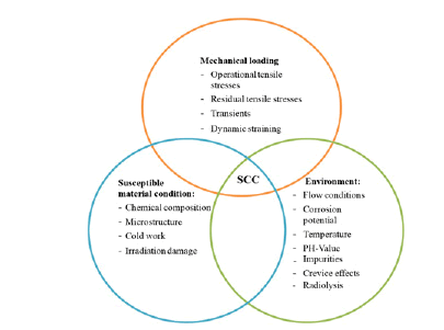
PWSCC is the initiation and propagation of intergranular cracks through the material in a seemingly brittle manner, with little or no plastic deformation of the bulk material and without the need for cyclic loading. It generally occurs at stress levels close to the yield strength of the bulk material but does not involve significant material yielding. PWSCC occurs when three controlling factors: material susceptibility, tensile stress, and the environment, are sufficiently severe Fig. 1. Increasing the severity of any one or two of the three factors can result in PWSCC occurring, even if the severity of the remaining factor or factors is not especially high.
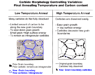
Material, extensive work has been performed on Alloy 600 base metals, grade 132/82/182. This work has shown that two main factors that affect PWSCC are chromium content and annealing temperature. Alloy 600 has the chromium content of 14 to 17%. The chromium content is not high enough to resist the PWSCC. Annealing temperature allow the carbine to dissolve easily to the grain boundary of the material. The grain can grow to the larger area which reduces the tensile stress on the surface of the material. A schematic representation of the carbide precipitation process for nickel alloys is shown in Fig. 2. [5].
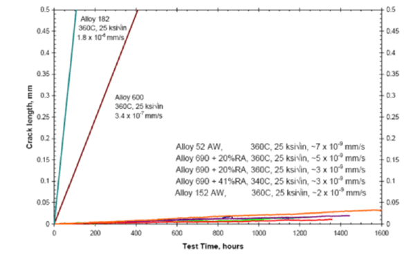
APR1400, weld metal of alloy 82/182 and base metal of Alloy 600 are not used in RCPB applications. Weld metals of alloy 52/52M/152 and base metal of Alloy 690 are only used for RCPB applications. Alloy 690 base metals are thermally treated to enhance their resistance to PWSCC, figure 3 shows comparison of crack growth rates (CGR) for alloy 182 weld metal and alloy 600 base metal (based on industry standard curves and adjusted to 360 oC) and alloy 152/152 weld metals and alloy 690 [10].
Figure 3 – SCC CGR in Ni alloys in PWR primary water [10].
Stress: Sustained high tensile stresses are required for PWSCC. There are two main sources of tensile stress: operating condition stresses due to pressure, temperature, and other mechanical loads, and weld residual stress; For the operating condition stresses, they cannot be changed readily as the working condition need to follow specified ASME Code Section III. However these stresses do not affect the condition and the appearance of PWSCC as most of the components are designed to withstand these stresses. For the weld residual stress, much work can be done to reduce the intensity of the stress. The weld residue stress is the combination of different aspects such as welding technique (GTAW or SMAW), welding workman experience (2-10 years), welding condition (indoor or outdoor).
Environment: The main environmental parameters are the temperature and the hydrogen concentration fig. 4, and to a much lesser extent the Li-content, interior related pH-value, and the presence of zinc. The effect of hydrogen on the crack growth rate in alloy 600 and its weld metals has been extensively studied during the last few years. It has been shown that the crack growth has a weak maximum in alloy 600, larger in the case of the weld metal alloys 182 and 132, at a hydrogen concentration approximately corresponding to the Ni/NiO equilibrium potential.
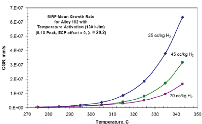
The effect of temperature shows that crack initiation and growth is faster for the increasing temperature. the CGR increases significantly with temperature. The effect of temperature on CGR and hydrogen concentration as shown in figure 5. CGR affected by hydrogen, the CGR has greater in the case of alloys 132 and 182 weld metal and a weak maximum in alloy 600 [11].
Figure 5 – Temperature Effect on PWSCC CGR for alloy 182 [11].
SUSCEPTIBLE MATERIAL CONDITION
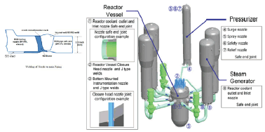
PWSCC refer to cracks found in the Piping System of RCS which consists of Reactor Vessel, Pressurizer, Steam Generator and Reactor Coolant Pump. Fig. 6 shows the location of cracks that are found at Primary Coolant Loop of Reactor [5],
Most PWSCCs are found within the area of welding between different materials and different component parts connected together. For example the Nozzle of Reactor Vessel joins to the main Piping, the Piping to the Pressurizer or Steam Generator or Reactor Coolant Pump. The welding consists of four different materials.
- Reactor Vessel: Low carbon graded steel: SA 508, class 2
- Safe End to Main Piping: austenitic stainless steel: SA 376, 304SS
- Butter: austenitic stainless steel, alloy 600, grade 182
- Weld bead: austenitic stainless steel, alloy 600, grade 82/182
Alloy 600 Base Metal
Alloy 600 is a nickel-based Alloy (72% Ni minimum, 14-17% Cr, 6-10% Fe) with high general corrosion resistance that has been widely used in Light Water Reactor (LWR) power plants (i.e., in PWRs and BWRs). In PWR plants, Alloy 600 has been used for steam generator tubes, CRDM nozzles, BMI nozzles, etc.
Citation: A A Abdallah K, Nagla T, et al. (2021) PWSCC mitigation for life management. J Def Stud Resour Manage. shows the status of PWR plant with respect to Alloy 600 nozzles in Korea. The RPV upper head of Kori Unit 1 was replaced in 2013, also the upper heads of Kori Unit 2 and Hanbit Unit 3, 4 are scheduled to be replaced. It is noted that BMI nozzle repair is very difficult due to the nature of access to the region. Thus, PWSCC of BMI nozzles represents a potential risk.
Table 1 - The Status of Alloy 600 Nozzles in PWRs in Korea [12].
| No | Plant | Power MWe | Start operation | Upper Head Nozzle | BMI Nozzle | RCS Inlet/Outlet Nozzle |
|---|---|---|---|---|---|---|
| 1 | Kori 1 | 587 | 1978 | Alloy 690 | Alloy 600 | Alloy 600 |
| 2 | Kori 2 | 650 | 1983 | Alloy 600 | Alloy 600 | Alloy 600 |
| 3 | Kori 3 | 950 | 1985 | Alloy 600 | Alloy 600 | Alloy 600 |
| 4 | Kori 4 | 950 | 1986 | Alloy 600 | Alloy 600 | Alloy 600 |
| 5 | Shin Kori 1 | 1000 | 2011 | Alloy 690 | Alloy 690 | Alloy 690 |
| 6 | Shin Kori 2 | 1000 | 2011 | Alloy 690 | Alloy 690 | Alloy 690 |
| 7 | Shin Kori 3 | 1400 | 2016 | Alloy 690 | Alloy 690 | Alloy 690 |
| 8 | Shin Kori 4 | 1400 | 2019 | Alloy 690 | Alloy 690 | Alloy 690 |
| 9 | Shin Wolsong1 | 1000 | 2012 | Alloy 690 | Alloy 690 | Alloy 690 |
| 10 | Shin Wolsong1 | 1000 | 2015 | Alloy 690 | Alloy 690 | Alloy 690 |
| 11 | Hanbit 1 | 950 | 1986 | Alloy 600 | Alloy 600 | Alloy 600 |
| 12 | Hanbit 2 | 950 | 1987 | Alloy 600 | Alloy 600 | Alloy 600 |
| 13 | Hanbit 3 | 1000 | 1995 | Alloy 600 | Alloy 600 | Alloy 690 |
| 14 | Hanbit 4 | 1000 | 1996 | Alloy 600 | Alloy 600 | Alloy 690 |
| 15 | Hanbit 5 | 1000 | 2002 | Alloy 600 | Alloy 600 | Alloy 690 |
| 16 | Hanbit 6 | 1000 | 2002 | Alloy 600 | Alloy 600 | Alloy 690 |
| 17 | Hanul 1 | 950 | 1988 | Alloy 600 | Alloy 600 | Alloy 690 |
| 18 | Hanul 2 | 950 | 1989 | Alloy 600 | Alloy 600 | Alloy 690 |
| 19 | Hanul 3 | 1000 | 1998 | Alloy 600 | Alloy 600 | Alloy 690 |
| 20 | Hanul 4 | 1000 | 1999 | Alloy 600 | Alloy 600 | Alloy 690 |
| 21 | Hanul 5 | 1000 | 2004 | Alloy 690 | Alloy 690 | Alloy 690 |
| 22 | Hanul 6 | 1000 | 2005 | Alloy 690 | Alloy 690 | Alloy 690 |
| 23 | Shin Ulchin1 | 1400 | Under construction | Alloy 690 | Alloy 690 | Alloy 690 |
| 24 | Shin Ulchin2 | 1400 | Under construction | Alloy 690 | Alloy 690 | Alloy 690 |
| Total | 13 Units | 14 Units | 6 Units | |||
Alloys 82 and 182 Weld Metal
Weld Alloys 82 and 182 have been commonly used to weld Alloy 600 to itself and to other materials. These Alloys are also used for nickel-based alloy weld deposit (buttering) on weld preparations and for cladding on areas such as the insides of reactor vessel nozzles. Alloy 82 is bare electrode material and is applied using the Gas Tungsten Arc Welding (GTAW) process (also known as Tungsten Inert Gas (TIG)
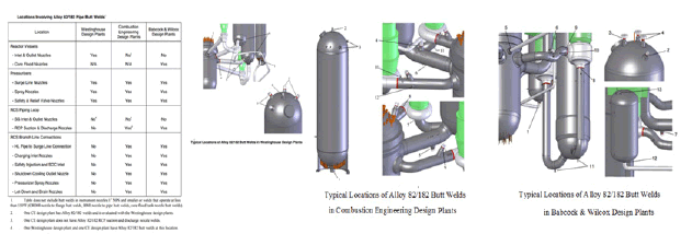
welding). Alloy 182 is a coated electrode material and is used in Shielded Metal-Arc Welding (SMAW). The compositions of the two Alloys are somewhat different, leading to different susceptibilities to PWSCC. Alloy 182 has lower chromium (13–17%) than Alloy 82 (18–22%) and has a higher susceptibility to PWSCC, apparently as a result of the lower chromium content. Most RCS welds, even if initiated or completed with Alloy 82 material, have some Alloy 182 material, figure 7 shows the Locations Involving Alloy 82/182 Pipe Butt Welds
SOURCE/Materials Reliability Program: Primary System Piping Butt Weld Inspection and Evaluation Guidelines (MRP-139)
source/ Materials Reliability Program: Primary System Piping Butt Weld Inspection and Evaluation Guidelines (MRP-139), EPRI, Palo Alto, CA: 2005. 1010087
INDUSTRY EXPERIENCE WITH PWSCC
The nuclear industry has experienced many cracked nozzles and welds, expensive inspections, more than 100 heads replaced and several plants with several-month outage extensions to repairing leaks. In addition, a plant was forced to shut down for more than two (2) years due to extensive corrosion adjacent to a PWSCC crack. Methods of inspection, repair, and replacement have already been developed since CRDM nozzle problems and solutions are well-known in Korea.
A reactor vessel bottom leak was discovered at South Texas Project (STP) Unit 1. The nozzles were repaired by removing their lower portions and replacing them with new nozzles made of the more corrosion-resistant Alloy 690. This “half-nozzle replacement” method had previously been employed as reviewed and approved by the NRC. To date, there are no experiences of PWSCC in BMI nozzle in Korea. Consequently, the tools needed to respond to emergent BMI issues and to manage the BMI PWSCC concerns may not yet be established.
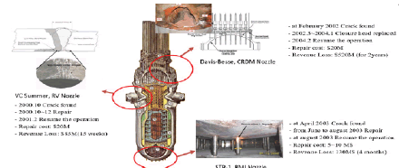
figure 8 shows cases of PWSCC in reactor vessel, and table 2.1 gives summary of this cases [3-5]. Two main factors affect PWSCC are chromium content and annealing temperature, Alloy 600 has the chromium content of 14 to 17%. The chromium content is not high enough to resist the PWSCC, table 2.2 shows chemical composition of Ni-base Inconel 600 and 690 materials [9].
Methodology to reduce PWSCC
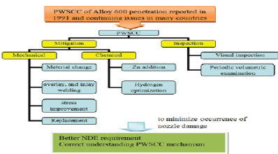
Fig. 9 summarizes the management strategies for PWSCC of Alloy 600 penetration nozzles. Basic management strategies to minimize the occurrence of damage to RCS piping consist of proper operation guidelines, inspection and monitoring or maintenance, and an assessment of degradation.
Corrective actions include material changes, corrosion resistant cladding, weld material changes, design changes, weld overlays, stress improvements, environmental improvement, mechanical repair, and component replacement. Detailed information for these corrective actions is described in the guidelines of IAEA Technical Report No. NP-T-3.13 [5], NUREG-0313; Rev. 2 [6], and the pertinent governing requirements or guidance documents for the plant.
Nozzle material change: SCC in Alloy 600 instrumentation nozzles of pressurizers was found in France in 1989. It was recognized that the cracking was a generic problem for 14 French 1300MW units equipped with Alloy 600 instrumentation nozzles [7]. Due to the high operating temperature and high level of residual stresses from manufacturing, nozzles, and their welds were replaced as rapidly as possible. The replacement with austenitic stainless was conducted regarding the good field experience with stainless steel nozzles and weldments on pressurizers in French 900MW units and elsewhere. All the repair processes were developed and qualified and personnel trained before the field operations.
Weld material change: Smith et al. reported in 1985 [9]; the results of reverse U-bend tests in conditions representative PWR primary water. Alloy 600MA cracked after 2000 h, while Alloy 690TT did not crack after 13,000 h in the beginning of the cycle chemistry. Alloy 600MA cracked after 2500 h, while Alloy 690TT did not crack after 16,000 h at the end of cycle chemistry. These results imply PWSCC resistance improvement factors of Alloy 690 TT greater than 6.5 and 6.4 for the beginning and end of the cycle chemistries, respectively. Changing the welding material is more economical to carry out. Alloy 690 with Chromium content of >30% has been tested and applied in the working environment. Alloy 690 will replace alloy 600 as a welding material in the RCS.
Stress: To be considered an effective PWSCC mitigation process, the Stress Improvement process must significantly modify the residual stress field at the weld location. For the uncracked weld condition, this is accomplished by producing sufficient compressive stress on the ID wetted surface such that, when sustained operating loads are added, the stress on the inside pipe surface remains compressive. The presence of the compressive stress inhibits initiation and propagation of PWSCC. Historically, SI must be followed by qualified volumetric or surface examinations to be fully credited as a mitigative measure. If cracks are found, they must be sized both in depth and length by procedures and personnel qualified to perform sizing evaluations. regarding. Examples of qualified SI that have been applied in light water reactors (LWRs) include:
Other SI processes such as surface conditioning (burnishing, laser peening) can be used as they become available and qualified (if they can be shown to develop sufficient compressive residual stress such that compressive stress exists on the inside surface during normal operation). For the cracked condition, Stress Improvement can still be applied to crack length with less than 10% of circumference and depth with less than 30% of the wall thickness. The requirement for the Stress Improvement process to be effective on a cracked component is that the stress intensity factor must be negative at the crack tip. The stress intensity factor must include residual stress and all sustained operating loads (primary and secondary). Stress Improvement effectiveness also must be shown on a weld repaired as-welded condition unless it can be definitively shown that no weld repairs exist.
Zinc Addition water chemistry: Laboratory tests have demonstrated that zinc appears to extend the time to crack initiation and may retard crack propagation rates of active PWSCC.The addition of soluble zinc additives to PWR primary water leads to the incorporation of zinc in the nickel ferrite films and the inner chromite layers that form on nickel based alloys exposed to primary water. The main goals of using zinc injection are: (a) reducing the dose rates and deposited radionuclide activities, (b) mitigation of PWSCC Alloy 600 components, and (c) a reduction of the axial offset anomaly (AOA). Westinghouse studied the zinc addition for PWSCC mitigation since 1990. Initial studies indicated that the zinc injection into primary water delayed the initiation of PWSCC and reduced the dose rate [5].
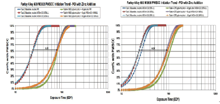
As of 2008, there are over 24 of 69 PWRs in the USA injecting zinc and the number of additional plants that are injecting zinc has been increasing as PWSCC becomes a more significant ageing degradation mechanism. The zinc addition was first applied in a Korean plant in April 2011 as a target concentration of 5 ppb, and the utility has a plan to expand the process to other Korean plants. The zinc application started in 1994 and by 2010 it was applied in over 70 PWRs worldwide (20% of all NPPs). A demonstration project at Southern Nuclear Operating Company's Farley Unit 2 showed that the addition of 35-45 ppb Zinc to the primary coolant resulted in lower radiation dose rates and an apparent decrease in PWSCC of Alloy 600 steam generator tubing. The Zinc had no significant effect on fuel cladding corrosion and Figure 10 shows Comparison of Farley Alloy 600 Heat for 1800 and 175 ppb~mo Zinc Addition.
Optimized Hydrogen Water Chemistry: Attanasio demonstrated the benefit of higher hydrogen levels for SCC mitigation [14]. Specifically, if one postulates an initial condition of 25 cc/kg H2O at 325°C, the calculated SCC growth rate for Alloy EN82H is 0.39 mils/day. If the hydrogen level is adjusted to 50 cc/kg H2O at the same temperature, the calculated SCC rate is 0.11 mils/day, which represents a decrease of 3.5 times. This benefit is significant, as can be seen by comparing the temperature reduction that would be needed to produce a similar benefit with decreasing 325–297°C using thermal activation energy of 130 kJ/ mole.
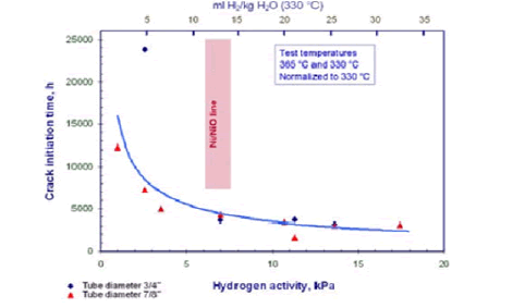
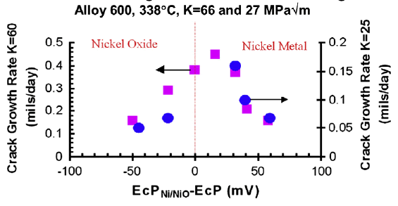
Fig. 11 is an example of the PWSCC growth depending on the hydrogen content at 325°C for Alloy 600, and a benefit with respect to crack growth of an increase of the hydrogen content at for Alloy 600 is shown in the graph [15].
The maximum crack growth rate obtained at corrosion potentials equivalent to the Ni/NiO stability line shifts to lower hydrogen concentrations when the temperature decreases. Using such data, there is now a trend in the USA and other countries, following their water chemistry practices, to increase the hydrogen content in the primary system. Many utilities are already operating closer to the higher specification limit than before.
On the other hand, operation at much lower levels is also being considered in Japan; they consider that lowering hydrogen may give better condition of PWSCC initiation [15]. According to Dozaki [16], a high hydrogen concentration of 15 and 25 cc/kg H2O did not give a big difference in PWSCC initiation time of Alloy 600 MA (less than 10% of initiation time difference). In the water with 5 cc/kg H2O, however, the PWSCC initiation time was about 50% longer than that of 15 and 25 cc/kg H2O conditions.
Results and Discussion
Due to safety of the plant, it became very clear the importance of study occurrence RCS issues specially the cracking in the RCS piping and find ways to prevent or mitigate it. Our team divided into areas to better evaluate the RCS piping and propose a methodology for inspection and maintenance.
- Inspection & PWSCC
- Stress Analysis
- Safety Inspection System Engineering
- Overlay & Inlay Welding
- In pipe Inspection & Maintenance
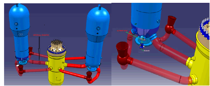
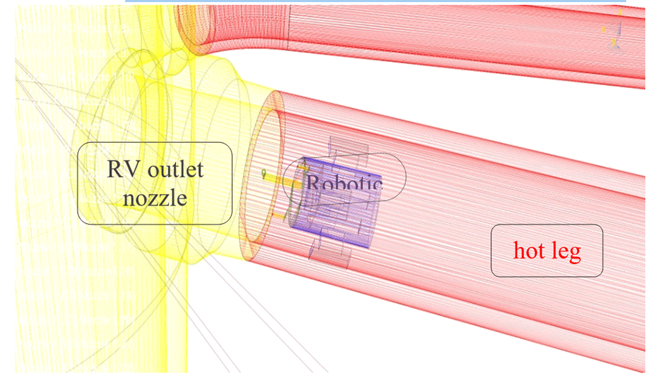
Modeling of PWR RCS: A 3D model of RCS using CATIA V5 is shown in Figs 7 and 8 that allow a virtual 3D simulation of the operation. This approach allows a virtual walk through to verify the proposed RCS inspection system. Fig. 12, 13 shows detail of nozzle weld inspection arrangement of robot and control.
References
- IAEA, â??Assessment and Management of Ageing of Major Nuclear Power Plant Components Important to Safety: Steam Generators,â? Vienna, International Atomic Energy Agency nuclear energy series, ISSN 1011-4289; IAEA-TECDOC-1668, (2011).
- Nuclear Code â??Kerntechnischer Ausschuss,â? website (www.kta-gs.de).
- IAEA, â??In-Service Inspection of Nuclear Power Plantsâ?, Safety Series No. 50-P-2, IAEA Manual, 1991, pp. 3.
- Kossiakoff, A. and W.N. Sweet, â??Systems Engineering: Principles and Practice,â? Wiley-Interscience, Hoboken, NJ, pp. 69-109, (2011).
- IAEA, â??Stress corrosion cracking in light water reactors: good practices and lessons learned,â? Vienna, International Atomic Energy Agency nuclear energy series, ISSN 1995â??7807; no. NP-T-3.13, STI/PUB/1522, PP.5-10, (2011).
- S. Hazelton, W. H. Koo, â??Technical Report on Material Selection and Processing Guidelines for BWR Coolant Pressure Boundary Piping,â? NUREG-0313; Rev. 2, (1988)
- Boudot, â??Stress Corrosion Cracking of Pressurizer Nozzles in French 1300 MW (e) units,â? (Proceedings Fontevraud II, France, 1994) SFEN, Paris, (1994).
- EPRI-1009801, Materials Reliability Program (MRP), â??Resistance to Primary Water Stress Corrosion Cracking of Alloys 690, 52, and 152 in Pressurized Water Reactors,â? (MRP-111), EPRI, Palo Alto, CA, USA, (2004).
- Smith, A. Klein, P. Saint-Paul, J. Blanchet, â??Inconel 690 A material with improved corrosion resistance for PWR steam generator tubes,â? in: Proceedings of the Second International Symposium on Environmental Degradation of Materials in Nuclear Power Systemsâ??Water Reactors, Monterey, California, September 9â??12, (1985).
- ASME, â??ASME Code Case N-766- Mitigation activity,â? (2011).
- Paul J. Kreitman, P.E., â??Mitigation and repair of reactor vessel inlet/outlet nozzel using weld inlay process,â? Westinghouse electric company, PCI Energy service, Lake Bluff 60048, (2007).
- Mitsubishi Heavy Industries, Ltd. (MHI), â?? Advanced INLAY System for Reactor Vessel of PWR,â? E-Journal of Advanced Maintenance, Vol.4, No.3, NT49, (2009)
- Paul J. Kreitman, P.E., â??Mitigation and repair of reactor vessel inlet/outlet nozzel using weld inlay process,â? Westinghouse electric company, PCI Energy service, Lake Bluff 60048, (2007).
- A. Attanasio, D.S. Morton, â??Measurement of the Nickel/Nickel oxide transition in Niâ??Crâ??Fe alloys and updated data and correlations to quantify the effect of aqueous hydrogen on primary water SCC,â? LM-03K049, Lockheed Martin, Schenectady, NY 12301, (2003).
- http://www.jsm.or.jp/ejam/Vol.4No.3/NT/NT49/article.html.
- Dozaki. D. Akutagawa, N. Nagata, H. Takiguch, K Noring, E-jornal Adv. Maint. 2 (2010) 65-76.
- Blanchard, B.S., and W.J. Fabrycky, â??Systems Engineering and Analysis,â? 5th ed. Prentice-Hall International series in Industrial and Systems Engineering. Englewood Cliffs, NJ, USA: Prentice-Hall, pp. 142-161, (February 2010)
- INCOSE, â??Systems Engineering Handbook,â? version 3.2.2., INCOSE-TP-2003-002-03.2.2., pp. 61-218, (October 2011).
- http://www.diakont.com/solutions/nuclear-energy/robotics/remote-welding-robotics/, specification sheet
- http://www.diakont.com/solutions/nuclear-energy/nuclear-pipe-services/rodis-crawler/, specification sheet.
- http://www.ocrobotics.com/
- Henry Offer; Hsueh-Wen Pao, Saratoga; William Dale Jones, Phoenix. â??Method and apparatus for remotely inspection and/or for remotely inspection and/or other components used in reactor coolant systems or other process applications,â? Pub. No.: 2009/0307891 A1, pp. 1-2, (December 2009
 Spanish
  Chinese
  Russian
  German
  French
  Japanese
  Portuguese
  Hindi
Hindi 