Research Article, J Electr Eng Electron Technol Vol: 7 Issue: 3
Development of 45W Q-band Space Qualified TWTs
Qu B, Liang X, Guo C, Shang Y and Feng J*
Beijing Vacuum Electronics Research Institute, Vacuum Electronics National Lab 100015, Beijing, China
*Corresponding Author : Jinjun Feng
Beijing Vacuum Electronics Research Institute, Vacuum Electronics National Lab 100015, Beijing, China
Tel: + 861084352320
E-mail: fengjinjun@tsinghua.org.cn
Received: September 04, 2018 Accepted: October 16, 2018 Published: October 23, 2018
Citation: Qu B, Liang X, Guo C, Shang Y, Feng J (2018) Development of 45W Q-band Space Qualified TWTs. J Electr Eng Electron Technol 7:3. doi: 10.4172/2325-9833.1000170
Abstract
Beijing Vacuum Electronics Research Institute (BVERI) has developed a series of Ka band space traveling wave tubes (TWTs) with saturation power of 12-100 W and efficiency of 55-63% for data transmission and communication for both conduction and radiation cooling. Recently Q-band space TWTs with conduction-cooled and space qualified are developed which are capable of delivering over 45W saturated RF power with overall efficiency exceeding 45%. This paper gives the main technical characteristics of Q-band space TWTs’ design, performances and qualification tests over 5.5 GHz bandwidth.
Keywords: Q-band; Space traveling wave tubes; Reliability
Introduction
Next-generation satellite systems need high-reliability millimeterwave amplifiers for downlink broadband communications to amplify and transfer a great deal of RF signals from routine satellite to terrestrial and satellite to satellite communications systems [1]. With the increasingly congested Ka-band, moving to the Q-band spectrum (40 GHz downlink) is a global trend to increase data rate. Because of the excellent efficiency and reliability to compared Solid State Power- Amplifiers (SSPAs), Travelling wave tube amplifiers (TWTAs) are still the preferred high power RF amplifiers on board of communication satellites operating in the Q-band. TWTAs can satisfy the satellite communications systems and support a high number of active channels without driving the platform into unreliable high temperature ranges or vibration conditions for other SSPAs more sensitive components [2]. To meet this response in the next available frequency Q-band for space application, Thales Electron Devices (TED) has started the development in Q-band for the medium and high power class TWTs of about 40W from 37.5 GHz-39.5 GHz (TH4607) to 100Watts from 37 GHz-40 GHz (TL40100) [3]. L-3 Communications Electron Technologies Inc. (L-3 ETI) also has many space qualified TWTs at millimeter-wave frequencies including 200 watts from 28 GHz-40 GHz (9928H) and100-watts from 36 GHz-50 GHz (9922H) [4,5]. Besides, Also BVERI has extended varieties of millimeter wave space TWTs from K-band to Q-band. Compared with TH4607, our Q-Band serial of space TWTs has broadened the bandwidth over 5.5 GHz, with the saturated RF out power more than 45 W, and increasing overall efficiency from 45% to 48% on Continuous Wave (CW) operation. The proto-type of TWT CC-280-1 has already completed full of space flight qualification test such as voltage extremes, random/sine vibration, shock, centrifugal acceleration, thermal cycling, thermal vacuum cycling and so on. Altogether with accurate simulation and qualification test verification, our Q-band Space TWTs are finally confirmed as the characteristics of high efficiency, reliability and long-life. The TWTs performance has well attracted attention to fulfill the actual needs for upcoming wireless satellite communication requests in this power level of 40W.
Experimental
Design for reliability
We have developed millimeter wave space TWTs for over 14 years and a serial of TWTs have been developed including tubes at different power level of 12 W-100 W at Ka-band, 45 W-60 W at Q-band, and 30 W at V-band. The longest in-orbit operation time up to now for one single Ka-band space TWTs has been over 26,000 Hours, which is still in-orbit with other 25 in-orbit millimeter wave space TWTs [6]. The typical properties are efficiency of 60% level, phase shift of 45 degree, IM3 of 9.5 dB maximum at input power back-off (IBO) -3 dB in the desired band packaged with conduct cooling or radiation cooling. They have been used as a baseline for designs of high efficiency, linearity and structure reliability in Q-band space qualified TWTs.
For gun design, low perveance of 0.13 p electron gun makes the beam focus difficult, but it’s helpful to extend cathode lifetime. The gun for Q-band has been designed and optimized by Opera code with beam current 45mA and beam waist radius 0.08 mm at cathode voltage 9.1 kV. The cathode is an M-type dispenser cathode [7] working at the temperature of 1000 and less than 2 A/cm2 current density [8]. The electron gun is designed with dual anodes and one focusing electrode. The second anode as an ion barrier can prevent positive ion backward bombardment to the cathode [9] and the isolated focusing electrode is used to modulate and compress the electron beam. SmCo magnets with higher magnetic energy product (BHmax191 kJ/m3) and lower reversible temperature coefficient (CT200 × 10/) are used in the PPM system [10-13]. Benefit from Opera simulation electron beam trajectory, the Q-band model of electron beam transmission rate is over 99% and the helix current decreases below 1.0 mA.
For Delay-line system design, the helix inner radius should be small enough to attain a high beam - wave interaction efficiency. In order to broaden the bandwidth, the dispersion curve is designed to be very flat. Due to the higher frequency at Q-band, the helix inner radius is less than 0.25 mm for higher interaction impedance. The copper plated wu-wire helix is loaded by three BeO ceramic supporting rods [14]. The optimized helix Dynamic Velocity Taper (DVT) and sever design have been used to enhance the energy transfer from wave to beam and suppress the harmonic and backward-Wave oscillation [15].
For RF coupling system, the input and output RF coupling system is WR22 standard waveguide and a pillbox window in which a thin sapphire or diamond film [16]. For this broad bandwidth operation, simulations using CST Microwave Studio that the RF output Power return loss of the system is below -20 dB in Figure 1 was shown with dot dash line compared to its input of -15 dB with solid line, and both lines of low-loss transmission characteristic S-parameters performance is over 6GHz at the Q-band frequency range between 37 GHz-to-43 GHz. Those RF coupling system ensures the well matched transmission between the helix and load to maximize output power and minimized the RF losses.
Results and Discussion
The Four-Stage Depressed Collector with Mo coated OFHC electrodes have been used to recover the spent beam energy from the delay line system [17], and the second electron yield has been reduced to 0.65 which reduce the effect of secondary electrons backflow. MTSS simulation of the collector shows that it provides high recovering efficiency of over 87% [18]. The outer surface of the ceramic collector is metallized, and welded with a copper cylinder, which increases the contact welding area between the collector outer surface and the baseplate to improve the capacity of heat dissipation and reliability for TWT thermal operation.
Performance test
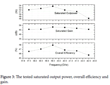
Based on above designed for reliability, all the components are integrated reasonably and tightly in the Q-band TWT which can meet the wide range of frequencies, power/gain levels, and environmental extremes requirements of space flight application. The Q-band Engineering Qualified Model (EQM) TWT CC-280-1 was packaged with conduct cooling shown in Figure 2. The Q-band space TWT reaches maximum output power of 54 W with over bandwidth of 5.5 GHz from 37 GHz-to-42.5 GHz, saturation gain over 45 dB and overall efficiency of 45% shown in Figure 3. The typical performance of Qband TWT is shown in Table 1.
| Saturate out power | ≥ 45 W |
| Package type | conduction-cooling |
| RF I/O | WR22/ WR22 |
| Operating cathode voltage | 9.1 KV |
| Total current | ≤ 52 mA |
| Mass | 0.83 kg |
| Dimension | 310 (mmL) × 60 mm(WÃ¯Â¼Â‰× 53 mm(H) |
| Bandwidth | 5.5 GHz |
| Helix current | ≤ 1.0 mA |
| Overall efficiency | ≥ 45% |
| Sat gain | ≥ 45 dB |
| Sat phase@Sat | ≤ 48 degree |
| AM/PM@Sat | ≤ 4 deg/dB |
| C/3IM-3dBSat | ≥ 9.5 dB |
| Noise figure | ≤ 35 dB |
| Power dissipation | ≤ 122 W |
Table 1: Typical operating parameters and performance of q-band space TWT CC-280-1.
The Q-band space TWT of 45 W is capable of processing up to 122 W of power dissipation at helix voltage of 9.1 kV, with 45 dB nominal saturated gain, 48 degree maximum non-linear phase shift, 4 deg/dB maximum AM/PM Conversion (-20 dB to Sat), only calling for the input power of less than 5 dBm (Figure 4).
In term of the mechanical techniques on helix processing, the saturated output power of all the three TWTs is over 46.6 dBm (45 W) across the operating frequency band, while the gain compression is under 8 dB and the helix current maintains a slight fluctuation in the level of 0.8 mA with IBO variation shown in Figure 5.
The Q-band TWT CC-280-1 represents the advanced millimeterwave TWTs series in BVERI shown in Table 2, which demonstrates the wide broad band, desirable out power and overall efficiency levels, insensitive helix current variations, acceptable mass and dimensions for supporting space flight mission.
| Parameter | CC-270-1 | CC-271-6 | CR-271-1 | CC-270-4 | CC-271-2 | CC-280-1 | |
|---|---|---|---|---|---|---|---|
| Frequency-band | K(Ka)-Band | K(Ka) -Band | Ka-Band | Ka-Band | Ka-Band | Q-Band | |
| Bandwidth (GHz) | 0.5 | 2 | 0.8 | 1.1 | 1.5 | 5.5 | |
| Power (W) | ≥20 | ≥100 | ≥100 | ≥30 | ≥55 | ≥45 | |
| Overall efficiency (%) | 50 | 55 | 60 | 50 | 55 | 45 | |
| Helix current (mA) | 0.3 | 0.8 | 1 | 0.5 | 0.5 | 0.8 | |
| Helix current@+8 dB to Sat (mA) | 1 | 1.5 | 1.2 | 1.2 | 1.2 | 0.95 | |
| Dimensions (m3) | 305 × 60 × 45 | 330 × 150 × 60 | 310× 60 × 55 | ||||
| Mass (kg) | 0.82 | 0.9 | 1.1 | 0.82 | 0.82 | 0.83 | |
| RF input | WR42 | K2.92 | K2.92 | WR34 | WR34 | WR22 | |
| RF output | WR42 | WR51 | WR51 | WR34 | WR34 | WR22 | |
| Package type | C.C. | C.C. | R.C. | C.C. | C.C. | C.C. | |
Table 2: Typical performance of MM-wave space TWTS in BVERI.
Qualification test
Following the standard test flow shown in Figure 6, the Q-band TWT CC-280-1 is required to be qualified from test on ageing and fatigue, voltage extreme deviation tolerance, sine/random vibration, centrifugal acceleration movement, shock response, thermal cycling and thermal vacuum cycling in sequence. The specific qualification level is listed in Table 3.
| Test | Range/Limit | Notes |
|---|---|---|
| Ageing | 80°C (baseplate temp.) | 500 hours duration |
| Fatigue | Ambient temp. | 750 hours duration |
| Voltages extreme deviation tolerance | Cathode Voltage Variation margins of 5%, Collector Voltages Variation margins of 10%, Anode voltage overload+100 V | 24hr/times |
| Random vibration | 16.7 gms12.8 gms// | 2 min/axis |
| Sine vibration | ±14.5 mm(4-15 Hz),13 grms (15-100 Hz) | 4 oct/min |
| Centrifugal acceleration | 10 gms | 2 min/axis |
| Shock (SRS) | 1600 gms | 3 times/axis |
| Thermal cycling | Normal pressure, -35°C/+85°C (Baseplate temp), at least 1.5 cycles for 4 hours duration at lowest and highest temp. | TWT operating |
| Thermal vacuum | 1 × 10⁻⁵ torr, -35°C/+85°C (Baseplate temp), at least 20.5 cycles for 4 hours duration at lowest and highest temp. | TWT operating, Cold start-up at -30°C (baseplate temp) |
Table 3: Model qualification test summary of Q-Band Space TWT.
At these qualification tests intervals, TWT CC-280-1 should be measured key parameters such as VSWR, output power and helix current compared with the full parameters test reference to verify performance consistency and measurement repeatability.
During final qualification testing, the model of 45 W-Q-band TWT CC-280-1 was cycled in a vacuum chamber at pressures of less than 1 × 10⁻⁵torr. Thermal vacuum cycling profile a total 20.5 cycles temperature range from -35 to +85 survival for operating more than 200 hours. In Figure 7, the curves show the RF out power at six frequencies in the whole process of the 20.5 thermal vacuum cycles, the power at the frequency band has little fluctuation with around 4 W maximum variation and 0.5 mA maximum helix current variation.
The 45 W Q-band space qualified TWT CC-280-1 performance matched the reference acceptance test performance at all intermediate tests and at the final full parameters test event.
Conclusion
BVERI has made Q-Band space qualified TWTs for flight with high reliability and efficiency with power of 45 W and broad bandwidth over 5.5 GHz. In addition, Electrical/Thermal and Mechanical margins already validated on the 45 W Q-band space TWTs’ design for reliability and demonstrated in-orbit coming soon to guarantee full mission compatibility.Further research needs to be done including the flexible power level, and the improvement of overall efficiency.
References
- Aloisio M, Angeletti P, Coromina F, De Gaudenzi R (2012) Exploitation of Q/V-band for future broadband telecommunication satellites. IEEE Vacuum Electronics Conference, Monterey.
- Kornfeld GK, Bosch E, Gerum W, Fleury G (2001) 60-GHz Space TWT to address future market. IEEE Trans Electron devices 48:68-71.
- Kupidura D, Vasseur F, Laurent A, Ehret P, Bosch E (2015) Thales 45W and 100W Q-band conduction cooled travelling wave tubes. IEEE International Vacuum Electronics Conference, Beijing.
- Robbins NR, Dibb DR, Menninger WL (2013) mm-wave space helix TWT performance and experience. IEEE International Vacuum Electronics Conference, Paris.
- Robbins NR, Dibb DR, Menninger WL, Zhai X, Lewis DE (2012) Space qualified, 75-Watt V-band helix TWTA. IEEE International Vacuum Electronics Conference, Monterey.
- Qu B, Liang X, Feng J, Yan G, Guo C, et al. (2017) Development of millimeter-wave space TWTs in BVERI. IEEE International Vacuum Electronics Conference, London.
- Bo Q, Feng J, Liu M, Shang Y (2012) Development of the K- band 100 W TWT with radiation cooling collector. IEEE International Vacuum Electronics Conference, Monterey.
- Liang X, Chen B, Qu B, Li L (2013) Development of Ku-band 150 W spaceTWT. IEEE International Vacuum Electronics Conference, Paris.
- Shi X, Fan H, Song F, Zhao X, Wan S, et al. (2013) Performance degradation simulation for M-type cathode based on ion bombardment. IEEE International Vacuum Electronics Conference, Paris.
- Qu B,Feng J, Liang X, Zhao Q, Liu M, et al. (2013) Development of K-band 50% efficiency 30W helix TWT. IEEE International Vacuum Electronics Conference, Paris.
- Marinescu M, McGinnis K, Liu JF, Walmer MH (2008) High (BH)max permanent magnets with near-zero reversible temperature coefficient of Br. International Workshop on Rare Earth Permanent Magnets and Their Application, Crete.
- Chen CH, Gong W, Walmer MH, Liu S, Kuhl GE (2002) Behavior of some heavy and light rare earth-cobalt magnets at high temperature. J Appl Phys 91: 8483-8485.
- Ji C, Yang J, Mao W, Yang Y, Li W, et al. (1998) High performance 2:17 type SmCo permanent with low temperature coefficients. Solid State Commumications 108: 667-670.
- Gilmour AS (2011) Klystrons, traveling wave tubes, magnetrons, crossed-field amplifiers, and gyrotrons. Artech House.
- David JF, Bariou D (2013) A 3D large signal model for helix TWT. IEEE International Vacuum Electronics Conference, Paris.
- Ding MQ, Li L, Bai G, Hu Y, Feng J (2011) A study of free standing diamond films for mm TWTs. IEEE International Vacuum Electronics Conference, Bangalore.
- Ding MQ, Qu B, Bai G, Xing J, Liang X, et al. (2011) Efficiency improvement of TWTs by surface modification of multistage depressed collectors. IEEE International Vacuum Electronics Conference, Bangalore.
- Liu M, Cai S, Feng J (2012) Design and simulation of a Q-band helix TWT. IEEE International Vacuum Electronics Conference, Monterey
 Spanish
  Chinese
  Russian
  German
  French
  Japanese
  Portuguese
  Hindi
Hindi 


