Spanish
  Chinese
  Russian
  German
  French
  Japanese
  Portuguese
  Hindi
Hindi Research Article, J Nanomater Mol Nanotechnol Vol: 11 Issue: 1
Deposition of Silver Nanoparticles Coatings on Stainless Steel by Thermal Decomposition of Silver (I) Citrate Ammonia Complex and Characterization of their Structural Properties
Abdallah Kamal AL-Hassan1, Rafi Mousa Jabrah2* and Ibrahim Assaad Ismail1
1Department of Chemistry, AL-Baath University, Homs, Syria
2Department of Applied Physics, Materials Sciences and Engineering, Higher Institute for Applied Sciences and Technology, Damascus, Syria
*Corresponding Author: Rafi Mousa Jabrah
Department of Applied Physics Materials Sciences and Engineering, Higher Institute for Applied Sciences and Technology, Damascus, Syria
E-mail: jabra2094@gmail.com
Received date: 20 March, 2023, Manuscript No. JNMN-23-92355;
Editor assigned date: 22 March, 2023, PreQC No. JNMN-23-92355 (PQ);
Reviewed date: 05 April, 2023, QC No. JNMN-23-92355;
Revised date: 08 January, 2024, Manuscript No. JNMN-23-92355 (R);
Published date: 15 January, 2024, DOI: 10.4172/2324-8777.1000389
Citation: AL-Hassan AK, Jabrah RM, Ismail IA (2024) Deposition of Silver Nanoparticles Coatings on Stainless Steel by Thermal Decomposition of Silver (I) Citrate Ammonia Complex and Characterization of their Structural Properties. J Nanomater Mol Nanotechnol 13:1.
Abstract
Silver Nanoparticles (NPs) coatings were prepared on Stainless Steel S.S316L substrate by thermal decomposition of silver (I) citrate ammonia complex based on aqueous solution of Silver Nitrate (AgNO3), in the presence of ammonia functional groups as complexing agent during the synthesis process and using citric acid as a stabilizer. After the coating deposition process, the coating samples were thermally treated for one hour at 400°C and 600°C. The crystal lattice constant of the deposited metallic silver was calculated from the X-Ray Diffraction (XRD) pattern, and the grain size has been determined using Debye- Scherrer relation. The dislocation density, the number of unit cell, the theoretical density and the morphology index of the silver coatings treated at 400°C and 600°C have also been determined. These coatings were characterized using SEM, EDX, to study their thickness and chemical composition, and Raman spectroscopy to study the nature of different bonding in these coatings.
Keywords: Silver NPs; XRD; Peak indexing; Raman spectroscopy; Density
Keywords
Silver NPs; XRD; Peak indexing; Raman spectroscopy; Density
Introduction
The great importance of Silver Nanoparticles (Ag NPs) is related to their functionalities and applications in various fields of science and technology, such as antibacterial activities, catalysis, conductive silver inks substituting Printed Circuit Boards (PCBs) technology, fluorescence. In recent years, several techniques have been developed to synthesize silver nanoparticles [1]. Methods of synthesis include physical, chemical, and biological methods like DC magnetron sputtering, RF magnetron sputtering, pulsed laser deposition PLD, laser ablation, gamma irradiation, electron irradiation, and electroplating method [2]. Chemical methods (wet chemistry) involve reduction of Silver Nitrate (AgNO3) or Silver Chlorate (AgClO4) aqueous solutions using different kind of reducing agents, such as hydrazine, ascorbic acid. On the other hand, Sodium Borohydride (NaBH4) at near water freezing temperature, Hydroxylamine (NH2OH) at room temperature and Formaldehyde (HCHO) in the presence of Polyethylenimine (PEI) as stabilizer have also been used during the synthesis process [3]. Polyvinyl Pyrrolidone (PVP) was used almost exclusively as the protective agent during synthesis. Green synthesis and photochemical methods have also been tested [4]. In addition to the previous methods, thermal decomposition of different silver precursors have been extensively studied, such as the thermal decomposition of silver carbonate, silver acetate by thermionic electron gun, and silver oleate complex. Most of silver nanoparticles synthesis methods show certain processing complication, and need specific equipment to produce quantities of these NPs [5].
In the binary Ag-O system, silver can form different oxidation state compounds like Ag2O, Ag3O4, AgO, Ag4O3. Among these different compounds, Ag2O is the most stable [6]. The oxide AgO decomposes into Ag2O and oxygen at temperatures of (100°C to 160°C), and by continuing heating to temperatures exceeding 350°C, Silver Oxide (Ag2O) decomposes into metallic Ag and oxygen.
In this work, the deposition of silver nanoparticles on Stainless Steel S.S 316 L substrates has been done by dip coating and thermal decomposition of silver (I) citrate ammonia complex from silver nitrate and citric acid in the presence of ammonia functional groups as complexing agent. The effect of heat treatment at different temperature of 400°C, 600°C on the crystal structure and morphology of silver coatings has been studied [7].
Experimental section
Substrate: The square shaped S.S316L alloy steel substrates measuring (1.5 cm × 1.5 cm × 1.5 mm) were polished using silicon carbide papers ranging from 200-1000 grit, after which the substrates were cleaned using ultrasonic sample cleaning equipment and acetone solvent for 20 minutes at 35°C, then substrates were washed with distilled water and dried [8]. The chemical composition of the used S.S316L steel was (wt.%): (C-0.03; Cr-17.2; Ni-10.2; Mo-2.05; Mn-1.3; Si-0.3; P-0.02 ≥; S-0.003 and Fe-balance). S.S316 L class was selected for the absence of any phase transitions during the heat treatment of the envisaged silver coatings [9].
Materials and Methods
Silver Nitrate (AgNO3) of 99.8% purity from CODEX CARLO ERBA, Citric Acid Monohydrate (C6H8O7.H2O) of (99.5% to 100%) purity from chem-lab and Dry Ammonia (NH3.H2O) of (25%) purity from (SCP) Surechem Products were used, as received from their suppliers, as raw materials for the preparation of Ag nanoparticles [10].
Preparation of silver (I) citrate ammonia complex
Aqueous solution of Silver Nitrate (AgNO3) with a concentration of (0.01 M) was prepared by dissolving (1.6987 g) of silver nitrate in (10 ml) distilled water until the dissolution process is complete. After this stage, (0.7 g) (0.00333 M) of Citric Acid Monohydrate (C6H8O7.H2O) was dissolved in (10 ml) distilled water and added to silver nitrate solution [11]. This mixture was mixed for half an hour, then the acidity of the solution was adjusted from the value (pH=2.54) to the value (pH=7.2) by dropping Ammonia (NH3.H2O). This makes the final solution milky in appearance. As silver citrate dissolves in nitric acid, the precipitate Ag3C6H5O7 does not appear, and silver citrate is able to decompose into silver and to easily disperse in water with the presence of ammonia functional groups as complexing agent [12]. Figure 1 shows silver (I) citrate ammonia complex. The previous steps mechanism could be described according to the following equations (1-4):
3AgNO3+H3C6H5O7→Ag3C6H5O7+3HNO3-----(1)
HNO3+NH3→NH4NO3---------------(2)
3Ag++ 6NH3→3(Ag(NH3)2)+----------(3)
(C6H5O7)3-+3(Ag(NH3)2)+→(C6H5O7)(Ag(NH3)2)3-----(4)

Figure 1: Silver (I) citrate ammonia complex.
Preparation of silver coatings on S.S316 L substrates
The films were prepared by dip coating of S.S316L substrates into silver (I) citrate ammonia complex solution with a withdraw rate of 3 mm/sec. The resulting coatings were dried at 100°C for 10 minutes, and then thermally heated in air at a rate of 5°C/min up to two different temperatures, the first at 400°C for 1 hour and the second at 600°C for 1 hour. The drying and heat treatment of the coatings were carried out in the furnace Hobersal S.L model HM-230 PAD P, Spain [13].
Characterization of S.S316L substrate and silver coatings
Crystallographic properties of S.S316L substrate and silver coatings were measured by X-Ray Diffraction (XRD) using Philips analytical diffractometer type (PW3710) with Cu-Kα radiation (λ=1,54060Å), generator settings (40 KV, 30 mA) at an angle of 2θ from 10.01°C to 79.99°C. The step size was 0.02° and the scan step time was 1st [14]. The diffraction pattern include information on the relative intensity of the peaks 1 (%), the diffraction angle 2θ (deg), (β) the full width at half maximum FWHM (deg), and values of inter-planar spacing d(Å) calculated from the Bragg’s law (1):
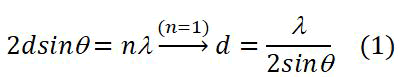
Where λ is the X-ray wavelength, λ=1.5406 Å.
For a cubic crystal system, the inter-planar distance dhkl between a given set of planes is defined in terms of their miller indices and the lattice constant a by the following relation (2):
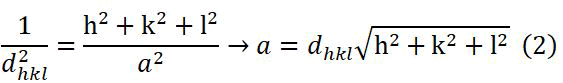
Where:
h,k,l=Miller indices, a is the lattice constant
dhkl=Inter-planar distance [15].
The values of the theoretical density is calculated from the X-ray diffraction patterns of silver coatings treated at 400°C and 600°C respectively, using equation (3):
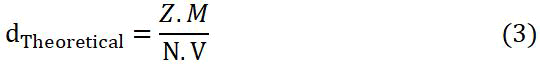
Where:
Z: Number of atom associated with each unit cell, (Z=4) for FCC
silver metal.
M: The atomic mass of the silver metal (M=107.8682 U).
N: Avogadro's number (6.02214076 × 10²³ mol-1).
V: Volume of unit cell (cm3).
The grain size of crystalline silver particles (D) was calculated by the Debye-Scherrer equation (4):
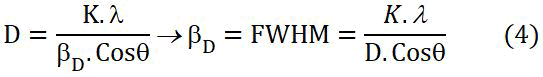
Where:
βD=Full width at half maximum FWHM (in Radian).
θ=BRAGG’S Diffraction angle (in degree).
K=Shape factor =0.9.
λ=X-Ray wave length (0.154056 nm).
The dislocation density of silver coating layers is determined using expression (5):
δ=1/d2----------(5)
The number of unit cell for the synthesized silver nanoparticles is calculated from equation (6):
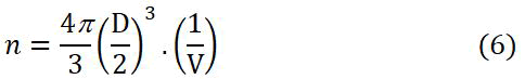
Where:
D=Crystallite size (nm)
V=Unit cell volume of the silver coating (nm3).
Morphology index is calculated from equation (7):
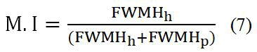
Where:
M.I=Morphology index.
FWHMh=Highest FWHM value obtained from XRD peaks.
FWHMp=Particular peak’s FWHM value for which M.I is to
be calculated [16].
The coating thickness was determined on cross-sectional images by Scanning Electron Microscopy (SEM) model TSCAN Vega-XMU, equipped with Energy Dispersive X-ray diffraction (EDX) to determine the chemical composition of the prepared coating. The surface morphology of the coatings was analyzed by Atomic Force Microscopy (AFM park scientific instruments autoprobe) [17].
Functional groups on the silver coatings on stainless steel were analyzed by Raman spectroscopy Horiba Jobin Yvon Lab Ram HR. The Raman spectra were collected in the region 100 cm-1-2100 cm-1.
Results and Discussion
X-ray diffraction analysis of S.S316 L and silver coatings
The X-Ray Diffraction (XRD) patterns of S.S316L stainless steel substrate and their silver nanoparticles coatings after heat treatment at 400°C and 600°C for one hour are shown in Figure 2 together with the respective reference XRD cards [18].

Figure 2: XRD pattern of S.S316L stainless steel substrate and its silver coating.
X-ray diffraction analysis of S.S316L stainless steel substrate
Table 1 shows the results of X-ray diffraction pattern of S.S316L stainless steel substrate. Peak indexing and lattice constant for S.S316 L stainless steel from diffraction angles θ (degree) are shown in Table 2 [19]. Application of equation number (2) on S.S316L stainless steel leads to the following lattice constant values at each diffraction peak: (2θ,a)=(38.3428°, 4.0628Å),(44.5945°, 4.0605Å),(64.9076°, 4.0601Å), and (77.9834°, 4.0609Å). The average lattice constant for S.S316L stainless steel is 4.0609 Å.
It is noted from Table 2 that the calculated value of the crystal lattice constant a, of S.S316L stainless steel substrate (a=4.0609Å) is greater than the regular value for S.S316L stainless steel which has an austenitic structure FCC corresponding to a lattice constant of (a=3.585Å). This may be related to the possibility of the stainless steel surface hardening with Nitrogen (N2) according to the absence of S.S316L stainless steel substrate peaks in the studied X-ray diffraction patterns of the silver coating layer is evident and this is related to the thickness of prepared silver coating [20].
| No. | Relative Intensity (%) | Height (cts) | 2θ (deg) | θ (deg) | FMWH β (deg) | d (Å) |
|---|---|---|---|---|---|---|
| 1 | 8.83 | 138.90 | 38.3428 | 19.1714 | 0.240000 | 2.34565 |
| 2 | 51.28 | 807.02 | 44.5945 | 22.29725 | 0.144000 | 2,03,025 |
| 3 | 100 | 1573.84 | 64.9076 | 32.4538 | 0.144000 | 1.43547 |
| 4 | 40.53 | 637.81 | 77.9834 | 38.9917 | 0.144000 | 1.22424 |
Table 1: Results of XRD pattern of S.S316L stainless steel substrate.
| 2θ (°) | Sin2θ | Sin2θ/3 | Sin2θ/4 | Sin2θ/8 | Sin2θ/11 | (hkl) | a (Å) |
|---|---|---|---|---|---|---|---|
| 38.3428 | 0.10784 | 0.03595 | 0.02696 | 0.01348 | 0.009804 | (111) | 4.0628 |
| 44.5945 | 0.14395 | 0.04798 | 0.03599 | 0.01799 | 0.01309 | (200) | 4.0605 |
| 64.9076 | 0.28796 | 0.09597 | 0.07199 | 0.03599 | 0.026178 | (220) | 4.0601 |
| 77.9834 | 0.3959 | 0.13197 | 0.09897 | 0.04949 | 0.03599 | (311) | 4.0603 |
Lattice 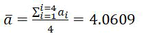 constant (Å) constant (Å) |
|||||||
Table 2: Peak indexing from diffraction angles θ for S.S316L stainless steel.
X-ray diffraction analysis of silver coatings
As can be seen from Figure 2, four diffraction peaks corresponding to (111), (200), (220) and (311) cubic structure planes of Face Centered Cubic (FCC) metallic silver were identified. These diffraction peaks are compared with the Powder Diffraction File (PDF No. 01-087-0597) which includes a crystal lattice constant equal to (a=4.0862Å). Table 3 shows that the experimental diffraction angle 2(θ) for silver coating heat treated at 400°C and 600°C and the standard diffraction angle (2θ) for silver in PDF No. 01-087-0597 are in agreement, this confirms the presence of (FCC) silver in the coating on S.S316L stainless steel substrate.
| Experimental diffraction angle (2θ in degrees) | Standard diffraction angle (2θ in degrees) for PDF (01-087-0597) | |
|---|---|---|
| 400°C | 600°C | |
| 38.15088 | 38.07468 | 38.115 |
| 44.27791 | 44.2682 | 44.299 |
| 64.44381 | 64.382 | 64.443 |
| 77.29051 | 77.39004 | 77.397 |
Table 3: Experimental diffraction angles of silver coating heat treated at 400°C and 600°C compared with standard diffraction angles.
Tables 4 and 5 show the results of X-ray diffraction diagram of the silver coatings deposited on the surface of S.S316L stainless treated at 400°C and 600°C, respectively.
| No. | Relative Intensity (%) | Height (cts) | 2θ (deg) | θ (deg) | FMWH β (deg) | d (Å) |
|---|---|---|---|---|---|---|
| 1 | 100.00 | 179.625500 | 38.150880 | 19.07544 | 0.144000 | 2.35700 |
| 2 | 40.90 | 73.466010 | 44.277910 | 22.13896 | 0.384000 | 2.04402 |
| 3 | 36.94 | 66.350880 | 64.443810 | 32.2219105 | 0.192000 | 1.44467 |
| 4 | 15.75 | 28.287340 | 77.290510 | 38.645255 | 0.288000 | 1.23347 |
Table 4: Results of XRD diagram of the silver coating treated at 400°C.
| No. | Relative Intensity (%) | Height (cts) | 2θ (deg) | θ ( deg ) | FMWH β (deg) | d (Å) |
|---|---|---|---|---|---|---|
| 1 | 100 | 432.228900 | 38.074680 | 19.03734 | 0.120000 | 2.36155 |
| 2 | 29.32 | 126.717100 | 44.268200 | 22.1341 | 0.288000 | 2.04445 |
| 3 | 23.47 | 101.452900 | 64.382000 | 32.191 | 0.144000 | 1.44591 |
| 4 | 14.72 | 63.633720 | 77.390040 | 38.69502 | 0.288000 | 1.23213 |
Table 5: Results of XRD diagram of the silver coating treated at 600°C.
For silver coating treated at 400°C, the main diffraction peaks are at 38.150880°, 44.277910°, 64.443810° and 77.290510°, while for silvercoating treated at 600°C, the main peaks are at 38.074680°, 44.268200°, 64.382000° and 77.390040°. From Tables 4 and 5, it can be observed that XRD peaks heights increase with increased heat treatment temperature. On the other hand, the Full Width at Half Maximum (FWHM) of diffraction peaks, is generally decreasing with temperature increase. The full width at half maximum of the (111), (200) and (220) diffraction peaks decreased from 0.144°, 0.384° and 0.192° respectively (for the silver coating treated at 400° for 1 h) to 0.120°, 0.288° and 0.144° (after treatment at 600°C for 1 h), this decrease of FWHM is related to an increase in the grain size of the silver coating particles.
Peak indexing for silver coatings treated at 400°C and 600°C from diffraction angles θ (degree) and inter-planar distance d (Å), are shown in Tables 6 and 7 respectively.
| 2θ (°) | θ (°) | 1000*Sin2θ | (1000*Sin2θ)/(35.21241) | (hkl) | a (Å) |
|---|---|---|---|---|---|
| 38.150880 | 19.07544 | 106.806615 | 3.033209457 | (111) | 4.08244 |
| 44.277910 | 22.138955 | 142.019025 | 4.033209457 | (200) | 4.08804 |
| 64.443810 | 32.221905 | 284.301972 | 8.073914055 | (220) | 4.08614 |
| 77.290510 | 38.645255 | 389.99611 | 11.07553019 | (311) | 4.09095 |
 Lattice constant. Lattice constant. |
|||||
Table 6: Peak indexing from θ (degree) for silver coating treated at 400°C.
| 2θ (deg) | d (Å) | 1000*1/d2 | (1000*1/d2)/(59.9367869) | (hkl) | a (Å) |
|---|---|---|---|---|---|
| 38.07468 | 2.36155 | 179.3105 | 2.99166≈3 | (111) | 4.0903 |
| 44.2682 | 2.04445 | 239.2473 | 3.99166≈4 | (200) | 4.0889 |
| 64.382 | 1.44591 | 478.3188 | 7.98038≈8 | (220) | 4.0896 |
| 77.39004 | 1.23213 | 658.6989 | 10.98989≈11 | (311) | 4.0865 |
 Å Lattice constant Å Lattice constant |
|||||
Table 7: Peak indexing from d-spacing for silver coating treated at 600°C.
It is clear that the division constant used in Tables 6 and 7 comes from the difference between the 2d and 1st diffraction angles (142.019025-106.806615=35.21241) and (239.247282-179.3104951=59.9367869), respectively.
The XRD pattern of silver coatings heat treated at 400°C and 600°C exhibit the most intense peak at (111) crystallographic plane, followed by other peaks at (200), (220), (311) planes respectively. No any diffraction peaks indicate the presence of impurities in the silver coatings. All the reflections confirm the pure silver metal with face centered cubic structure (a=b=c, α=β=γ=90°) and Fm3m (space group no.225).
The calculated crystal lattice constant value computed from x-ray diffraction diagrams for the silver coating layer heat treated at 400°Cis equal to (a=4.0868Å), while the value becomes (a=4.0888Å) for the silver coating layer thermally treated at 600°C. The calculated lattice constant of silver coating is very close to that in the PDF card (No. 01-087-0597).
It can be seen that S.S316L stainless steel substrate and silver coating layer heat treated at 400°C, 600°C respectively, have the same diffraction planes, namely (111), (200), (220) and (311) (Tables 6 and 7) and (Figure 2). The planes that were identified have identical characteristics where all of h, k and l are odd or even. The characteristics of such planes indicate that the structure formed is face centered cubic.
Metallic silver formation on stainless steel S.S316L
The formation of metallic silver Ag, and the absence of silver oxides (AgI2O, AgIIO, AgIII2O3) can be explained based on equation (5) and (6), respectively.
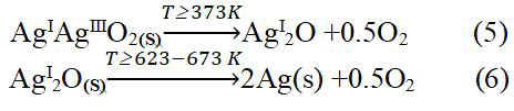
It is evident from the two previous equations that dissociation of mixed oxides (AgIAgIIIO2) into monoxide AgI2O occurs at T ≥ 373 K, while the transformation of AgIIO oxide into AgI2O oxide is in the range from (373 K-473 K), the oxide AgI2O is the most stable form up to temperature of 623 K. The obtained result is positively in agreement with the literature and scientific publications presented in the field of the study of the stability of silver oxide in equation (5) and (6), and with the hypothesis of the formation of metallic silver.
Calculation of silver coating theoretical density
Table 8 gives the values of the theoretically density calculated from the X-ray diffraction patterns for silver coating layer heat treated at 400°C and 600°C respectively using equation (3).
| Temperature | Lattice constant a (Å) | V=(a)3(cm3) | dtheoretically (g/cm3) |
|---|---|---|---|
| 400°C | 4.0868 | 6.8257464.10-23 | 10.49669 |
| 600°C | 4.0888 | 6.8357725.10-23 | 10.48129 |
Table 8: Theoretical density values calculated from X-ray diffraction pattern of silver coatings treated at 400°C and 600°C.
Calculation of grain size, dislocation density, number of unit cell
The calculated particle size, dislocation density and number of unit cell details for silver coating heat treated at 400°C and 600°C are shown in Tables 9 and 10 respectively.
The calculated particle size based on the Debye-Scherrer equation varies in the range from 22.33 nm to 58.37 nm and in the range from 29.77 nm to 70 nm for silver coating heat treated at 400°C and 600°C respectively.
The average dislocation density of silver is 8.7945 × 10¹⁴ m-2 and 5.9186 × 10¹⁴ m-2 as obtained from equation (5) for silver coating heat treated at 400°C and 600°C, respectively.
In X-ray line profile analysis was used to determine the intrinsic stress and dislocation density of silver nanoparticles synthesized through wet chemical sol-gel method, their value were found to be 0.275 GPa and 7 × 10¹⁴ m-2 respectively.
The dislocation density of silver nanoparticles prepared by electrolysis method was found to be 9.2 x 10¹⁴ m-2, and the dislocation density was 7.9 × 10¹⁴ m-2 for silver nanoparticles synthesized by wet chemical techniques.
Structurally, dislocations are a type of topological defect. Larger dislocation density is correlated with a larger hardness. Chen and Hendrickson measured and determined dislocation density and hardness of several silver crystals. They found that crystals with larger dislocation density were harder.
The average number of unit cell is calculated to be 0.712 million and 1.323 million of unit cell for silver coating heat treated at 400°C and 600°C respectively.
Figure 3 shows the relationship between dislocation density and grain size.
• The relationship between the number of unit cells and the grain size.
• The relationship between the dislocation density and number of unit
cell.
• Silver coatings treated at temperatures of respectively.
| 2θ (deg) | Particle size D (nm) | FWMH (radian) | Dislocation density δ=1/d2 (m-2) | Number of unit cell (n) |
|---|---|---|---|---|
| 38.150880 | 58.37404578 | 0.002513274 | 293.46 × 10¹² | 1.525006 × 10⁶ |
| 44.277910 | 22.33494987 | 0.006702064 | 2004.6 × 1012 | 0.085421 × 10⁶ |
| 64.443810 | 48.90901275 | 0.003351032 | 418.044 × 10¹² | 0.896972 × 10⁶ |
| 77.290510 | 35.3180163 | 0.005026548 | 801.691 × 10¹² | 0.337754 × 06 |
Table 9: Particle size (D), dislocation density (δ) and number of unit cell (n) for silver coating heat treated at 400°C.
| 2θ (deg) | Particle size D (nm) | FWMH (radian) | Dislocation density δ=1/d2 (m-2) | Number of unit cell (n) |
|---|---|---|---|---|
| 38.074680 | 70.03276656 | 0.002094395 | 203.890 × 10¹² | 2.629630 × 10⁶ |
| 44.268200 | 29.77890665 | 0.005026548 | 1127.67 × 1012 | 0.202170 × 10⁶ |
| 64.382000 | 65.18986436 | 0.002513274 | 235.309 × 10¹² | 2.120952 × 10⁶ |
| 77.390040 | 35.34256997 | 0.005026548 | 800.578 × 10¹² | 0.337975 × 10⁶ |
Table 10: Particle size (D), dislocation density (δ) and number of unit cell (n) for silver coating heat treated at 600°C.

Figure 3: a) Dislocation density versus grain size; b) Number of unit cell versus grain size; c) Dislocation density versus number of unit cell of silver coatings on the surface of S.S316l stainless steel treated at temperatures of 400°C and 600°C for 1 h.
Morphology Index (MI)
Tables 11 and 12 show the values of the morphology index calculated for silver coating treated at 400°C and 600°C respectively. From Tables 11 and 12, the value of the morphology index calculated for the silver coating treated at temperature 400°C varies in the range (0.27-0.67), but at temperature of 600°C the value of the morphology index increases to become within the range (0.5-0.71).
Figure 4 shows the relationship between M.I and grain size of silver coating treated at 400°C and 600°C respectively. It can be seen that at 400°C the value of the morphology index increases when the grain size are in the range (D=22.33 nm-48.91 nm), after which the increase in the grain size is associated with a decrease in the morphology index, i.e. when the value of the grain size becomes close to (D=58.374 nm), MI takes a value of (MI=0.273).
At temperature 600°C, the morphology index takes a constant value (MI=0.5) when the grain size is in the range (D=29.779 nm-35.343 nm). However, an increase in the value of the morphology index is noticed when the grain size become greater than (35.343 nm), where MI shows a value of (M.I=0.706).
| 2θ (deg) | Particle size D (nm) | FWMH (deg) | FWMH (radians) | Morphology index (unit less) |
|---|---|---|---|---|
| 38.150880 | 58.37404578 | 0.144000 | 0.002513274 | 0.272727 |
| 44.277910 | 22.33494987 | 0.384000 | 0.006702064 | 0.5 |
| 64.443810 | 48.90901275 | 0.192000 | 0.003351032 | 0.66666 |
| 77.290510 | 35.31801163 | 0.288000 | 0.005026548 | 0.571428 |
Table 11: Morphology index of silver coating treated at 400°C.
| 2θ (deg) | Particle size D (nm) | FWMH (deg) | FWMH (radians) | Morphology index (unit less) |
|---|---|---|---|---|
| 38.074680 | 70.03276656 | 0.120000 | 0.002094395 | 0.70588 |
| 44.268200 | 29.77890665 | 0.288000 | 0.005026548 | 0.5 |
| 64.38200 | 65.18986436 | 0.144000 | 0.002513274 | 0.66666 |
| 77.390040 | 35.34256997 | 0.288000 | 0.005026548 | 0.5 |
Table 12: Morphology index of silver coating treated at 600°C.

Figure 4: Morphology index versus particle size of silver coatin g treated at 400°C/600°C for 1 h.
AFM analysis
The surface morphology of silver coatings was analyzed by Atomic Force Microscopy (AFM). Figure 5 shows the AFM 3D image with 5μ × 5 μ scan of the silver nanoparticles coatings treated at temperatures 400°C and 600°C for 1 h respectively and grown on the S.S316L stainless steel substrate. AFM images show the granular nature of the particles spherical in shape. It is observed from the 3D surface image that the grains are not uniformly distributed, but rather agglomerate on the surface of the S.S316L stainless steel.

Figure 5: AFM 3D images of silver coating treated at temperature a) 400°C and; b) 600°C for 1 h on S.S316L.
SEM and EDX analysis
Scanning Electron Microscope (SEM) was used for studying cross section and the surface morphology of the silver coating. SEM image was obtained for silver coating deposited on S.S316L. Stainless steel substrate in order to study the thickness and surface morphology of silver coating. Figure 6 shows the SEM cross section image and Figure 7 shows SEM surface morphology of the silver coating treated at temperatures of 400°C and 600°C respectively.

Figure 6: SEM cross section image for silver coating treated at 600°C for 1 h.

Figure 7: SEM surface morphology for silver coating treated at temperature a) 400°C and; b) 600°C for 1 h.
The polygonal silver metal particles can be seen in Figure 7 with dimension of 2 μ ; 1μ ; 500 nm for silver coating treated at 400°C and 600°C respectively. A few triangular particles can be seen in Figure 7. The SEM cross-section study shows an average thickness of 8.6 μ on the surface of S.S316L stainless steel substrate, the elemental composition of the coating layer was determined using the (EDX) at 20 KV. Figure 8 shows EDX results for silver coating treated at temperature of 600°C for 1 h, the elemental analysis of surface coating proves the presence of silver metal with the peaks observed at 3.0; 3.2 and 3.4 KeV, and corresponding to the binding energies AgLα, AgLβ and, AgLβ2 respectively. The other elements that appear in the prepared coating layer on EDX spectrum are related to the composition of the S.S316L stainless steel substrate.

Figure 8: EDX spectrum of elemental composition of the silver coating treated at 600°C for 1 h.
Raman spectroscopic study of silver coating
Figure 9 shows the Raman spectrum of silver coating on S.S316L substrate and heat treated at 400°C and 600°C for 1 h.
Raman spectra shows Ag-N or Ag-O stretching band at 220 cm-1-228 cm-1.

Figure 9: Raman spectra of silver coating on SS316L substrate heat treated at 400°C and 600°C for one hour.
The two bands at 1360.6 cm-1-1336.9 cm-1 and 1575.8 cm-1-1596.7 cm-1 for coating layer heat treated at 400°C, 600°C for 1 h are attributed to the D and G bands of Graphene Oxide (GO), and are representative of sp3 and sp2 of carbon atoms on the GO, respectively. The slight increase in the ratio (ID/IG) from (0.8622) to (0.9963) indicates an increase in the deformation of the carbon lattice when graphene oxide is reduced to grapheme. The weak band shown at 906 cm-1-901 cm-1 is related to C-C stretching vibration. The two bands of weak intensity at 670.4 cm-1-681.7 cm-1 and 571.7 cm-1-573.2 cm-1 are ascribed to the rocking vibration ρ(O-CO) and out of plane deformation γ(O-CO), respectively. The δ(CCC) in plane deformation vibration band was observed at 287.3 cm-1.
Conclusion
Based on the above, silver coating was deposited on S.S316L stainless steel surface by a facile and reproducible method of thermal decomposition of silver (I) citrate ammonia complex based on aqueous solution of Silver Nitrate (AgNO3) in the presence of ammonia functional groups as complexing agent during the synthesis process. The X-ray diffraction diagrams allowed the identification of deposited silver nanoparticles, the calculation of crystal lattice constant, theoretical density, grain size, dislocation density, and the morphology index of the silver coating treated at the 400°C and 600°C. Calculations indicated a decrease in the dislocation density value with the increase in the heat treatment temperature of the silver coating layer. AFM 3D images and SEM examination of silver coating showed the granular nature of the prepared silver coatings with a thickness of 8.6 μ. Elemental analysis of the prepared silver coating layer using EDX technique confirmed the presence of silver metal on the surface of S.S316L stainless steel, and Raman spectroscopy characterization showed the nature of different bonding in silver coating.
Authors thank AL-Baath university administration (Homs, Syria) and higher institute for applied sciences and technology administration (Damascus, Syria) for facilitating the resources for achieving the present research work.
References
- Guzman M, Dille J, Godet S (2012) Synthesis and antibacterial activity of silver nanoparticles against gram positive and gram negative bacteria. Nanomedicine 8:37-45.
[Crossref] [Google Scholar] [PubMed]
- Jiang ZJ, Liu CY, Sun LW (2005) Catalytic properties of silver nanoparticles supported on silica spheres. J Phys Chem B 109:1730-1735.
[Crossref] [Google Scholar] [PubMed]
- Karthik PS, Singh SP (2015) Conductive silver inks and their applications in printed and flexible electronics. Rsc Advances 5(95):77760-77790.
- Xu H, Suslick KS (2010) Water soluble fluorescent silver nanoclusters. Adv Mater 22:1078-1082.
[Crossref] [Google Scholar] [PubMed]
- Asanithi P, Chaiyakun S, Limsuwan PJ (2012) Growth of silver nanoparticles by DC magnetron sputtering. J Nanomater 79:1–8.
- Marechal N, Quesnel EA, Pauleau Y (1994) Silver thin films deposited by magnetron sputtering. Thin solid films 241:34-38.
- Zakaria MA, Menazea AA, Mostafa AM, Al-Ashkar EA (2020) Ultra-thin silver nanoparticles film prepared via pulsed laser deposition: Synthesis, characterization, and its catalytic activity on reduction of 4-nitrophenol. Surf Interfaces 19:100438.
- Tsuji T, Thang DH, Okazaki Y, Nakanishi M, Tsuboi Y, et al. (2008) Preparation of silver nanoparticles by laser ablation in polyvinylpyrrolidone solutions. Appl Surf Sci 254:5224-5230.
- Long D, Wu G, Chen S (2007) Preparation of oligochitosan stabilized silver nanoparticles by gamma irradiation. Radiat Phys Chem 76:1126-1131.
- Bogle KA, Dhole SD, Bhoraskar VN (2006) Silver nanoparticles: Synthesis and size control by electron irradiation. Nanotechnol 17:3204.
- Mazur M (2004) Electrochemically prepared silver nanoflakes and nanowires. Electrochem Commun 6:400-403.
- Nickel U, Zu Castell A, Poppl K, Schneider S (2000) A silver colloid produced by reduction with hydrazine as support for highly sensitive surface enhanced Raman spectroscopy. Langmuir 16:9087-9091.
- Qin Y, Ji X, Jing J, Liu H, Wu H, et al. (2010) Size control over spherical silver nanoparticles by ascorbic acid reduction. Colloids Surf A: Physicochem Eng Asp 372:172-176.
- van Hyning DL, Zukoski CF (1998) Formation mechanisms and aggregation behavior of borohydride reduced silver particles. Langmuir 14:7034-7046.
- Leopold N, Lendl B (2003) A new method for fast preparation of highly Surface-Enhanced Raman scattering (SERS) active silver colloids at room temperature by reduction of silver nitrate with hydroxylamine hydrochloride. J Phys Chem B 107:5723-5727.
- Yang AL, Zhang ZZ, Yang Y, Bao XC, Yang RQ (2013) Synthesis of silver nanoparticles and the optical properties. Optoelectron Lett 9:1-3.
- Chou KS, Lai YS (2004) Effect of polyvinyl pyrrolidone molecular weights on the formation of nanosized silver colloids. Mater Chem Phys 83:82-88.
- Raveendran P, Fu J, Wallen SL (2003) Completely "green" synthesis and stabilization of metal nanoparticles. J Am Chem Soc 125:13940-13941.
[Crossref] [Google Scholar] [PubMed]
- Mallick K, Witcomb MJ, Scurrell MS (2004) Polymer stabilized silver nanoparticles: A photochemical synthesis route. J Mater Sci 39:4459-4463.
- Yoshikawa M, Yamada S, Koga N (2014) Phenomenological interpretation of the multistep thermal decomposition of silver carbonate to form silver metal. J Phys Chem C 118:8059-8070.